Содержание
- 1 Module development
- 1.1 1. Definitions
- 1.2 2. How to start
- 1.3 3. Module structure
- 1.4 5. Script part
- 1.4.1 5.1. Basics
- 1.4.2 5.2. Adding to store
- 1.4.3 5.3. Creating SubDevices
- 1.4.4 5.4. Creating Commands and Feedback Channels.
- 1.4.5 5.5. Creating Widgets and Remotes
- 1.4.6 5.6. Creating relations between wiget graphic items and driver channels.
- 1.4.7 5.7. Adapting modules for mobile devices.
- 1.4.8 5.9. Create scanner
- 1.4.9 Uploading modules to the store
Module development
1. Definitions
Module - is a component that allows you to control one type of equipment by its unique ID. The module is located in the store of modules.
Control panel (panel) - a device from which i3 lite projects are launched.
Static module - a module with fixed functionality (the functionality cannot be expanded at launch or during work).
Dynamic module - a module with dynamic functionality (it can be expanded at launch or during work). Such modules are considered more complicated in development, but they are more flexible.
Cloud storage - a cloud server for uploading ready modules.
iRidium studio - an editor which enables creation of modules to control devices for the i3 lite application.
i3 lite - an application to create, set and use i3 lite projects.
i3 lite project – an automation project made up of ready equipment control modules. i3 lite projects differ from i2 Control projects: i3 lite projects can be edited dynamically without prior editing in iRidium studio. i3 lite project consists of several small parts that can be put together into a single whole and easily edited in i3 lite app with the help of built-in constructor. A big number of intermediate processes, such as installing software on PC, uploading projects on contol panels are no longer necessary. All is done in one place - on a control panel.
SubDevice - a virtual view of the workspace of a physical device.
Room (in i3 lite) - a visual part of i3 lite containing widgets to control equipment.
Widget - a visual module component located in a room. It has limitaions is size and a fixed position in the room interface. It contains the main module functionality. Remote is used for additional functions .
Remote - a visual module component which is hidden by default. It opens only when a corresponding item of the widget is clicked. It does not have size limitations (not more than the panel display size) and can be located in any part of the room interface (it is usually located in the middle of the panel display). It contains additional module functions.
Macro - a sequence of control commands of different modules which is activate by clicking. It contains Action and Condition.
Scene - a sequence of control commands of different modules which is activated automatically when a particular event happens. It contains Event, Action and Condition.
Event - a scene component. It describes the control command and value range. When a value from the value range is sent the scene is activated.
Action - a component of macro commands and scenes. It describes the control command and value that is sent to the command. There are 2 types of Action: Simple Action and Advanced Action.
Simple Action - it is used when you know the command and Action value beforehand.
Advanced Action - it is used when you know the command beforehand but the value is unknown. The value is set dynamically when Action is used in i3 lite (but not when it is created in iRidium studio).
Condition - a component of macros and scenes. It describes the control command and value range. When a value from the value range is sent Action is executed.
Scanner - a software part, that analyzes any bus looking for connected devices. Found connected devices are displayed in a list. Modules for the found devices are downloaded from iRidium store and the devices become available to control in i3 lite.
2. How to start
Before starting your work, it is recommended to read iRidium documentation. It describes the basics of working with iRidium. The i3 lite documentation describes how to develop modules for the i3 lite platform for users, who already know iRidium. If you want to write script use i3 lite API.
The module life cycle consists of:
- Developing the graphic part in iRidium studio
- Developing the driver part (scripts, devices)
- Testing
- Publishing in iRidium store
- Using (module download via the i3 lite application from the cloud and adding to automation projects)
A module is created in iRidium studio.
The module consists of: the graphic and driver part. The module can be used on the server without any futher development.
Module creation.
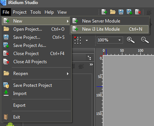
To create a module, start the editor, select File -> New -> New i3 lite Module.
When creating a module indicate: a project name and the module style, that can be later on changed by a user. After a module project is created and you can start the development. You have to consider that a module can work on smart phones and tablets.
3. Module structure
iRidium studio provides the following functions to create a module: SubDevice creation (section 3.1.); Widget creation (section 3.2.); Remote creation (section 3.3.); creation of Actions, events, conditions (section 3.4.) and the script part (section 3.5.).
3.1. SubDevice
From the definition it is clear that SubDevice is a virtual view of the workspace of a physical device. Many devices supports several work groups with the same functions. Each work group can be located in a separate zone. For full control over the zone SubDevice is created for each work group of the device. For example, 6-channels HDL dimmer contains 6 dimmable channels that can control 6 work groups. That's why, it is reasonable to create 6 SubDevices in the module to be able to create actions, events and conditions for each work group separatelly.
SubDevices in i3 lite modules are compulsory, their number can vary from 1 to many. Usually the number of SubDevices is equal to the number fo controller channels.
SubDevice consists of:
- Conditions
- Actions
- Events
- Widgets
Conditions, actions and events are SubDevice logic items. Macros and routines are created on their basis (more - section 3.4.). A widget is a graphic item. Users control SubDevices via widgets. Usually one SubDevice contains one widget but the number of conditions, actions and events varies (from 0 to many).
What to use: script or the editor?
There are two ways to create SubDevice (as well as Widget, Remote, Actions, Events and Conditions): with the help of the editor and with the help of scripts (see the methods in lite API). The editor is recommended when you know the number of SubDevices in the module beforehand (the static module) and this number is not big. Script is recommended when there are a lot of SubDevices and their manual adding in the editor will take a long time. Or when there is no information about the number of SubDevices in the module and it can vary (the dynamic module).
For example, there is a module for the light controller (dimmer), which can be connected to 4 work light groups at most. In this case it is adviable to add 4 SubDevices with the help of the editor. But in case of a module for the DMX controller (controller for controlling lights which can change their color), to which you can connect up to 512 work groups, creation of SubDevices with the help of the editor is not the best solution. Firstly adding 512 SubDevices will take o long time. Secondly, displaying512 wigets at a time is unnecessary, as many of them are unlikely to be used. In this case it is advisable to write a script which creates the required number of SubDevices.
With the help of the editor
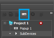
To create SubDevices with the help of iRidium studio, it is necessary to create a project, then to select the project in the tree and select the "SubDevices" item in it. After that the button for adding SubDevices becomes available.
Then you can add actions, events, condition and popups (widgets or remote) to the corresponding SubDevice.
SubDevice has the following properties:
Name - the SubDevice name;
Device - the name of a device to which SubDevice belongs (the property has to be filled in).
Read how to work with SubDevice with the help of scripts in section 5.2.
3.2. Widget
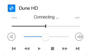
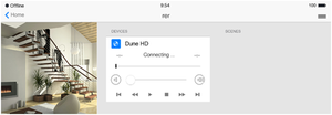
Widget is a visual module component of a popup type that is displayed in the room. The main task of a widget is to display the main items to control SubDevice and to enable trasfer to a remote control (Remote) of SubDevice. For example, to control a media-player a volume slider or the Mute button can be placed on a widget for fast access to volume adjustment. A weather widget can display the current weather and the remote control can have weather forecast for 5 days.
Without a widget i3 lite module has no sense, as it has no graphic presentation in i3 lite projects.
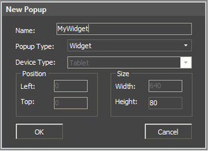
Wigets have a definite size:
- Width 640
- Height from 80
Creating wigets with the help of the editor.
Select the created SubDevice in the tree and mark the "Popups" branch. Then click the "Add popup page" button in the menu above the projects tree. In the appeared window select the popup type - "Widget", set the name and properties:
Graphic items have to used when creating a widget.
Items only from the Gallery can be used in i3 lite modules.
Properties of a created widget can be changed with the help of Object Properties.
Graphic items are assigned to channels like in popups:
Wigets can be also created and edited with the help of scripts (see lite API).
Use.
Widget is displayed:
- In a room when a client uses a project
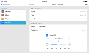
- In the module settings when it is added to the project.
3.3. Remote
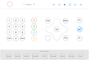
Remote (a remote control) is a graphical area to control SubDevices. Unlike wigets, it can have free size and position. And it is displayed on call. Remote is displayed when a button to go to the remote control is pressed on a widget.
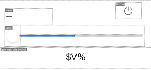
Items to control equipment are placed on Remote (buttons, lists, switches, levels). There can be from 0 to several remote controls. Example of Remote:
Remote is created like a Wiget (section 3.2). The only difference is o select "Remote" when you click "Add Popup Page" in the "Device Type" property.
As Remote is a standard popup, you can work with it in the same way (see iRidium Script API)
3.4.Conditions, Actions and Events
Conditions, Actions and Events are used in macros and routines. The way of working with them is similar to relating graphic items and driver channels. The only difference is that you have to click on graphic items for drivers to execute commands. When working with Actions, the set values, for example, 100 for the Volume channel, can be activated in the software. It enables communication of different drivers with each other. Besides that the saved Actions can be combined and formed into dynamic routines during application work. The routines are saved in the memory. The routines can also be assigned to graphic items and activated by clicking.
The number of Conditions, Actions and Events depends on the range of device functions and necessity to create routines and macros.
Creating Actions.
There are two types of Actions: Simple and Advance. The difference is that when a simple action is created all information for its functioning is already known. For example, to turn on a dimmer to full brightness, setDimmer channel is to be activates and 255 value is to be sent there. The value is known beforehand. Advanced action is created on the basis of incomplete information about the action. In case with the dimmer, the brightness is to be set at any value from 0 to 255, but it is not clear what value is to be sent and when it has to be sent.
Creating Events and Conditions.
Events determine what values of SubDevice channel a system can react to. If light in a room is on and it corresponds to the set 255 value of a dimmer channel, close the blinds.
Events and Conditions are identical in setting. The difference is the moment when data is recognized. Events are always monitored, and the moment the set value is received in the feedback channel, an event happens. For Conditions the value is checked on demand, for example, when an action is activated. Conditions never activate anything, but they are a condition for an action to happen.
Example of Condition:
If the light in the room is on and it is later than 6.00 PM, close the blinds. Thus, if the light in the room is on in the afternoon, blinds are not closed.
5. Script part
The script part has some aspects in the development of i3 lite modules. Before developing the script part of i3 lite modules we recommend that you read the basic rules for writing scripts in iRidium pro (link) and i3 lite API.
5.1. Basics
Modules can have an unlimited number of scripts or none of them. There are different types of scripts for modules:
- Driver - script files of this type contain scripts, responsible for working with a driver
- GUI - script files of this type contain scripts, responsible for working with graphics
- Common - script files of this type contain general scripts such as a set of additional functions or a description of classes of minor importance
- Setup - a special script file. that contains information about module settings, to be more exact, a list of fields that have to be filled in, types of these fields and functions to check if the entered data are correct.
Devision into types is necessary for the module correct work on the server, but the server knows nothing about the graphic part. That's why a module developer has to devide scripts into types. The server does not notice files for working with the graphic part.
When modules are developed module names have to be used instead of IR. Thus, a listener looks this way module.AddListener…
Every script file starts with a listener
module.AddListener(IR.EVENT_MODULE_START, 0, function(){});
It's a new type of events, designed for module development. When a module is developed remember that the script file is now closed for other script files. It means that now you identical names of variables and functions can be used in different script files and they are not rewritten. But there is a limitation. There is no simple accees to a function from another script files. To get access to a function from another script file, import a script file with the help of the following command module.Import("FileName.js")
5.2. Adding to store
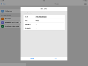
When a module is added from the store it requests device parameters (IP, port, etc.). For example, HDL GPRS, when it is added from the store, requests the following parameters:
To transfer these parameters to a module use the "Setup" script. Any script can be the "Setup" script - to achieve it tick the "true" check box in the script parameters:
For example, the "Setup" script for iRidium for HDL module looks this way:
{
	// Data to connect drivers, created in Project Device Panel
	Drivers:
	[
      {
         Name: "HDL-BUS Pro Network (UDP)",
         Properties:
         [
            {
               Type: "textfield",
               Name: "Host",
               DefaultValue: "255.255.255.255",
               Validation: function(in_sValue) {
                  var l_aValueHost = in_sValue.split(".");
                  if (l_aValueHost.length != 4) {
                     return "Please input correct Host";
                  } else
                     if (parseInt(l_aValueHost[0], 10)>=0
                        && parseInt(l_aValueHost[0], 10)<=255
                        && parseInt(l_aValueHost[1], 10)>=0
                        && parseInt(l_aValueHost[1], 10)<=255
                        && parseInt(l_aValueHost[2], 10)>=0
                        && parseInt(l_aValueHost[2], 10)<=255
                        && parseInt(l_aValueHost[3], 10)>=0
                        && parseInt(l_aValueHost[3], 10)<=255
                     )
                        return 0
                     else
                        return "Please input correct Host";
               }
            },
            {
               Type: "textfield",
               Name: "Port",
               DefaultValue: "6000",
               Validation: function(in_sValue) {
                 if(parseInt(in_sValue, 10)>=0)
                     return 0
                  else
                     return "Please input correct Port";
               }
            }
         ]
		}
	],

	// General information for the module (driver and generated by script)
	Module: [{
		Name: "Channels Count",
		Validation: function (in_sValue) {
			if (parseInt(in_sValue, 10)>=0)
				return 0;
			else
				return "Please input Count";
         }
      },
		{
         Type: "textfield",
			Name : "SubnetID",
			Validation : function (in_sValue) {
				if (parseInt(in_sValue, 10)>=0)
					return 0;
				else
					return "Please input SubnetID";
			}
		},
      {
         Type: "textfield",
			Name : "DeviceID",
			Validation : function (in_sValue) {
				if (parseInt(in_sValue, 10)>=0)
					return 0;
				else
					return "Please input DeviceID";
			}
		}

	]
}
The Setup files consists of 2 parts. The first part is driver settings. These settings request IP addresses, ports and logins to connect a driver to a device. The second part is general driver settings, such as the number of outputs, access keys. To set a field in the Setup, set the following fields in the script:
- Field type - indicate what field is to be displayed to a user (text field, data array, etc. More in API)
- Field name - the name of a field that a user sees when setting a module
- Default value - what value is to be entered by default
- Check function - a function that verifies the value in the field. A function that checks if the input data are correct has to be written.
These functions are to be used on the module script.
module.GetProperty("Field name")
Besides standard parameters, any parameters required for module initialisation can be requested:
5.3. Creating SubDevices
Let's see how to create dynamic subdevices via script in this example:
// Get the unique ID of the bus at launching
 module.AddListener(IR.EVENT_MODULE_START, 0, function(){
   var netWorkName = "HDL-BUS Pro Network (UDP)"';
   // Take the existing device and assign it ot the variable ''device''
   var device = module.getDevice(netWorkName);
   // Create a new subdevice with the following parameters:
   // Device - driver object
   // The name of the created subdevice, that will be used for calling this device and will be displayed to a user
   var NewSubDevice = module.addSubDevice({
       Device: device,
       DeviceName: "HDL Dimmer 1"
    });
 });
If a subdevice is created successfully, NewSubDevice variable will have the object of the created subdevice with the following operations:
- Work with subdevice widgets
- Work with subdevice commands and tags
- Work with с AEC(Actions, Events, Conditions)
5.4. Creating Commands and Feedback Channels.
There are two ways to create Commands и Feedback :
- Using the functions of iRidium studio
- Via scripts
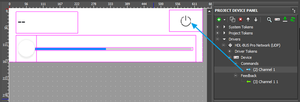
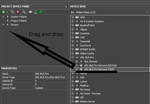
Let's see in detail how to create commands and feedback channels via the code. Before doing so you are required to connect the module in the PROJECT DEVICE PANEL tree:
To connect a module just drag and drop it as it is shown in the image.
Here is the code:
l_oSubDevice = module.AddSubDevice("Light " + count, HDL_SERVER, false, IR.SUB_DEVICE_TYPE_THROUGH_DIMMER);

// Adding channel StatusOnStart
if (count == 1)
 l_oSubDevice.AddChannel("Dimmer:statusOnStart", [parseInt(SUBNET_ID.toString(16), 16), parseInt(DEVICE_ID.toString(16), 16), HDL_CODES.singleChannelReadTarget, SEPARATOR, 0x0, 0x0, 0x0, 0x0, 0x1, 0x0, 0x1, 0xE8, 0x3, 0x0, 0x0]);

// Assigned to the variable name of the channel
var l_sChannelName = "Dimmer:channel" + count;

// Adding channels
l_oSubDevice.AddChannel(l_sChannelName, [parseInt(SUBNET_ID.toString(16), 16), parseInt(DEVICE_ID.toString(16), 16), HDL_CODES.singleChannelLigtning, SEPARATOR, parseInt(count.toString(16), 16), 0x0, 0x0, 0x0, 0x01, 0x0, 0x0]);
l_oSubDevice.AddTag(l_sChannelName, [parseInt(SUBNET_ID.toString(16), 16), parseInt(DEVICE_ID.toString(16), 16), HDL_CODES.singleChannelLigtning, SEPARATOR, parseInt(count.toString(16), 16), 0x0, 0x0]);

// Adding smart virtual tag
l_oSubDevice.AddVirtualTag("Power", 0, false, IR.SUB_DEVICE_COMMAND_POWER, true);
l_oSubDevice.AddVirtualTag("Power On", 0, false, IR.SUB_DEVICE_COMMAND_POWER_ON, true);
l_oSubDevice.AddVirtualTag("Power Off", 0, false, IR.SUB_DEVICE_COMMAND_POWER_OFF, true);
l_oSubDevice.AddVirtualTag("Level", 0, false, IR.SUB_DEVICE_COMMAND_LEVEL, true);
Commands and feedback channels created via scripts "are not displayed" in the PROJECT DEVICE PANEL tree.
5.5. Creating Widgets and Remotes
To create a wiget via the code and assign it to a particular subdevice, create a template of the wiget in the editor. A widget has a fixed size
- Width 640
- Height from 300
To indicate to the program that this popup is not a wiget, set False in the Widget field in Object Properties.
SubDevice.addWidget(in_Widget)
The input parameter of the method is in_Widget - an object, a popup, created in the editor before hand.
The output parameter of the method is True or False (successful or not).
For example, we have 3 lamps. Not to create a separate wiget for each lamp, use the ready template of a popup and clone it. Here is an example of creating wigets using the existing template with the help of the code.
The Clone method enables cloning existing popups.
Module.ClonePopup (in_Popup, in_Name)
The input parameters of the method:
in_Name - the new wiget name.
- in_Popup - the link to the popup.
The output parameter of the method is True or False (successful or not).
// Refer to the wiget you want to copy
  module = B.getModule(moduleID)
 var popup = module.GetPopup("Dimmer");
 for (var i = 1; i<=3; i++)
 {  // Create a wiget using cloning
  var widget = NewSubDevice.addWidget(Module.ClonePopup(popup, "Dimmer"+ i));
 }
Add a function to the dimmer which enables moving the slider:
// the user slider for the level
function UserSlider(Level, Slider)
 {
    Property = "X";
    Len = "Width";
    // Function for calculating the slider position in relation to the level
    function Move(){
       Slider[Property] = Level.Value * (Level[Len] -50) / 100;
    }
    // Subscription for events     IR.AddListener(IR.EVENT_ITEM_PRESS, Level, Move); // pressing on the level
    IR.AddListener(IR.EVENT_MOUSE_MOVE, Level, Move); // clicking on the level
    IR.AddListener(IR.EVENT_TOUCH_MOVE, Level, Move); // moving a finger on the level
    IR.SetInterval(600, Move);  // auto-update in 600 ms
}
The names of new widgets must be unique.
5.6. Creating relations between wiget graphic items and driver channels.
Relation between a graphic item and a channel is formed when relating the driver feedback channel (Feedback) and the graphic item created on the wiget. Here is an example of creating relations between graphic items of the created wiget and the driver channels with the help of the code.
module.AddRelation(in_Feedback, in_Graphic);
The input parameter of the method is
in_Feedback - the full path to the feedback channel in the string type (example: "Drivers.HDL-BUS Pro Network (UDP)" + ".HDL-MC48IPDMX.231:channel" + moduleID).
in_Graphic - the full path to the graphic item property in the string type (example: "UI.Dimmer" + ".level.Value").
The output paramerter of the method is True or False (successful or not).
5.7. Adapting modules for mobile devices.
As each module is to be used on different platforms, the graphic part of a module is to be done in 2 variants for tablets and smart phones. It means that Remotes are to be created for both a tablet and a smart phone. After two variants of Remotes are created, write a script that determones the current version of a panel (tablet or smart phone) and display the required popup.
 if (IR.DisplayType == IR.DISPLAY_TYPE_PHONE) { //If the module is used on a smart phone
    var l_oPopupScanner = module.GetPopup("Phone"); //Show popup created for smart phones
  }
 else {
   var l_oPopupScanner = module.GetPopup("Tablet");//If a module is used on a tablet, show a popup for tablets
 }
5.9. Create scanner
Scanner - a module that analyzes a bus and connected device. Connected devices are formed in a list. A module for a selected device is downloaded from the store and becomes available in i3 lite.
The structure of scanner work:
- A scanner is downloaded from the store;
- A user enters scanner parameters (IP, Port, etc.) these parameters are sent to the scanner script;
- After processing the input parameters, a scanner send requests to the bus to find devices ;
- The found devices are formed in a list;
- When a device in the list is selected, a scanner sends the parameters fo the selected device to a module.
Consider the following when developing a scanner:
- Scanner parameters when addign from the store;
- Scanner logics;
- Sending parameters of the selected device to the module;
- Module logics with reference to the parameters received from the scanner.
Scanner development is identical to developing a module. A graphic part and a script with logics have to be created for a scanner.
The main difference is that a scanner can work only on a control panel, it is never launched on a server. That's why there is no need to separate driver script from interface script.
When a scanner is developed, new logics of work appears. First, create a module to control a device. Then upload the module to the store of modules. When a module is uploaded, you see the unique ID of the module.
When you develop a scanner, write a script with the following logics:
- Creating a driver
- Searching equipment
- If equipment is not found, determine what equipment it is
- With the help of ModuleSetupFinish command (module ID, js object with setup settings of this module)
After this, the app downloads a module from the store and installs it.
Uploading modules to the store
To upload modules to iRidium store do the following:
- Go to My Account of a module developer at http://www.iridiummobile.net/approve/dev/
- Click “Add new module”, enter module name and its type (scanner or module)
- Enter information about the module
- Upload a module file in Development, if you upload a test version of a module
- Upload a module file in Production, if you want to open the module and start selling it
- Wait till a module is approved by a moderator
- A module appears in the store of modules

